|
| Search the GPIO manual: |
The MShift™ embedded code works with three gear variables:
The shift table is the heart of the MShift™ transmission control code's auto mode. This table lets the user define the optimal gear for any speed and load. The gear derived from the shift table is the target gear, and the controller will attempt to shift from the current gear to the target gear (if they aren't the same already, of course!). It make take one shift to reach the target gear, or it make take more shifts if the conditions are changing rapidly (and depending on the degree of smoothing employed).
A greatly simplified summary of the logic in auto mode looks something like this:
<infinite loop>lookup target gear in 16×9 shift table based on average load and current speed<loop again> |
The 16×9 shift table is effectively 9 load based shift tables that set the upshift/downshift speeds (and RPMs) by load. By having this arranged as one ascending 3-D table, it is much easier to see if you have any inconsistencies that could cause operational problems (like hunting between gears, which is frequently an issue with separate upshift and downshift tables).
In order to tuning the shifts, you need to do two things: set the shift points (by engine load and vehicle speed) and set the shift firmness.
Shifts happen when the current gear doesn't match the target gear (or if the manual gear is less than the current gear). This will initially happen when the speed or load matches one of the table's speed or load bin values. The speed bins will determine the pre-shift engine rpms. So you adjust the shift points by moving the table's gear entries at different speed bins, or by altering the speed bins themselves.
A properly tuned shift table will be the result of a number of factors. Some of these are fixed factors within the transmission like its internal gear ratios. Other fixed factors derive from the vehicle itself like the tire size, rear axle ratio, engine torque curve and RPM range, etc.. However a large number of factors are set by the intended application and driving style of the end user. So it's generally not a great idea just to take someone else's shift table and apply it to your situation, even if they have the same transmission and vehicle. It probably won't be optimal for the way YOU drive your car.
To fill in the table, you must decide what rpm you want to shift at at a given load. Start by determining the speeds that give the maximum engine RPM (i.e. redline) you want to shift at. You use this to calculate the speeds (you can use the calculator below) and put these speeds and gears into the top row of table. Then you fill in the intermediate values on that load row. For example, you may have determined that you want the trans to shift from first to second at WOT at 36 mph, and second to third at 66 mph, and fourth at 110 mph, as in the table below. So you would put a 1 in the first column of the row, then a 2 in the 36 mph column (you might have to edit the mph bins), and a 3 in the 66 mph column, and a 4 in the 110 mph column. Then you fill in all the values between 1 and 2 (i.e. in the 0 to 26 mph columns of the WOT row) with ones. And you fill in all the values between 2 and 3 with twos, etc.
You may have to juggle the 16 speed bins around to get the right speed for each of the shifts at all the differing loads. Bear in mind that shifts occur at the speed bin values because these only the only place that the target gear can change. So you will want to consider these carefully, and may need to tinker with them to suit your vehicle, its use, and your driving style.
There are some important facts to keep in mind:
For example, in the table below, and with a load of 100kPa, the upshifts will happen at:
Here is an example of a shift table for a 4L60E in a particular vehicle:
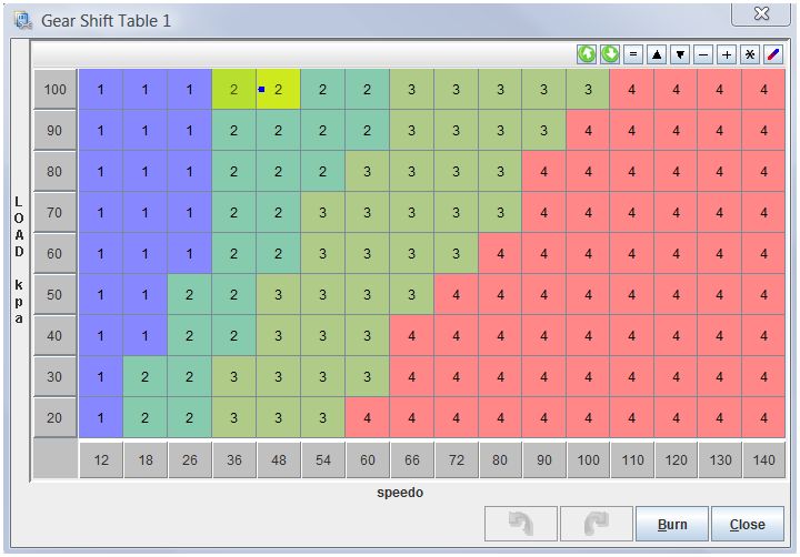
In this case, at 100 kPa, the 1st to 2nd shift will be at 36 mph. That's because the first cell in the 100 kPa row that has a 2 is in the 36 mph column.
The 2nd to 1st downshift will be at 35.9 mph, because the speed value is below 36, so the next lower bin is used (the 26 mph column) and this has a 1 in it for the gear.
This is neglecting the hysteresis, which can screw up the shift relative to the table if hysteresis is large, so you should keep it small - 2 to 3 mph.
In the table above (and at 100 kPa) the 2nd to 3rd shift will be at 66 mph, and the 3rd to 4th shift will be at 110 mph.
At 45 kPa, the shifts in the default table are:
If you accelerated up to 65 mph @ 100kPa with the table above, then let off the throttle so the speed remained the same, you would initially be in 2nd gear, but shift to 3rd once the averaged load dropped below 90 kPa (which it turns depends on the 'LOAD Smoothing Factor'), and then shift to 4th once it got below 30 kPa. Jumping on the throttle again would cause downshifts to 2nd (at anything above 90 kPa, of course).
Note that there are some general trends:
You might want to think of the shift table like this:
The black lines indicate the shifts. The bin values show the ranges for the speed and load for each target gear cell.
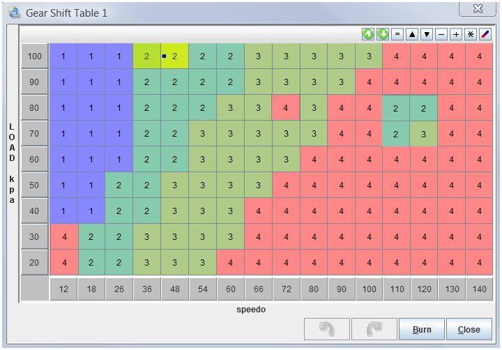
Here is an example of a misconfigured table that is going to cause problems:
Here is an example of the shift table in action:
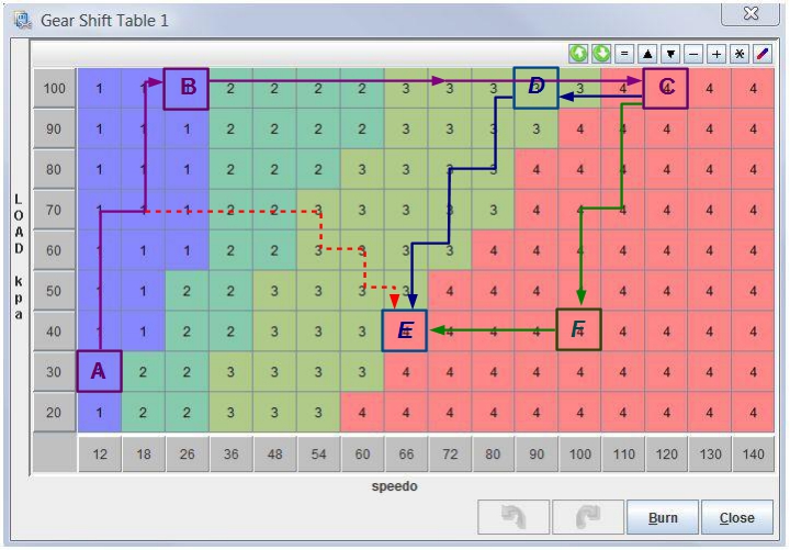
There are a number of paths on this table. The path A→B→C is the full throttle acceleration from a slow (or zero) speed to a 120+ mph through all the gears. The load at A is initially low, but climbs very quickly by B (because the load reacts to increases in load much faster than to decreases in load) and then stays constant until the acceleration stops at C. Note that moves UP the table imply an increase in load (i.e. higher driver demand) and moves to the right indicate acceleration (increasing speed).
So in the path A→B→C, the shift speeds are 36 mph for second, 66 mph for third, and 110 mph for fourth. These are near the redline for this vehicle.
Suppose we then let off the throttle at C and decelerate to 70 mph. The paths C→D→E and C→F→E both represent decelerations (to 70 mph) and reduced load (40 kPa). Note that C→F→E doesn't downshift to 3rd , unlike C→D→E, which does downshift to 3rd (then eventually upshift 4th ). The difference is that C→F→E has a smaller 'LOAD Smoothing Factor' which allows it to react to decreasing loads more quickly.
Why might you want C→D→E (with the larger load smoothing factor)? You would want this if you were going to accelerate immediately again, and wanted the engine revs in a range to give you maximum power (like in road racing) by downshifting as soon as possible. In fact, in a road race application, the trans might cycle only between C→D and D→C if the speeds were between 90 and 120 mph at all times. The trans would always be in the right gear coming out of corners.
Why might you want C→F→E (with the smaller load smoothing factor)? You would want this if you were going NOT to accelerate immediately again, and wanted the engine revs to return to a comfortable, fuel efficient range as soon as possible (possibly in drag racing for the shut down and return road, and perhaps for the highway so you could pass quickly and settle back into a cruise quickly).
Finally, note that the direct path A→E (dashed line) represents reasonable initial acceleration that decrease slowly up from a slow speed to 70 mph, without any WOT. The transmission will shift to 2nd at 36 mph, 3rd at 54 mph, and 4th at 66 mph. This is fairly representative of what a lot of drivers do when joining a freeway.
The key points are:
Note that we said above, "higher gears are achieved at lower speeds at lower loads and lower gears are selected as we move up the table loads." This is important so the the target gear isn't jumping all over the place, it has a rational progression. Separate tables would make it hard to see if there was a suitable progression, you would have to be comparing the tables to each of the others all the time. Having a 16×9 tables makes this easy to see at a glance.
For example, suppose we had a table like:

This table looks odd, and not surprisingly it acts odd. On the deceleration C→D→E notice that the target gear is 4th at C, then switches from 4th to 3rd , then back to 4th , then to 3rd , again to 4th , then finally 3rd at E as we decelerate. (Note that these shifts might not all actually happen, depending on things like the length of time for the shifts, the load average factor, hysteresis, etc.. In many cases the target gear will simply jump rapidly to the final cell, and the shifts will proceed as desired - one downshift to 3rd.) This oscillating target gear behavior is caused entirely by not following the guidelines noted above. But it might be hard to spot what was going on if there were 9 separate load tables on 9 separate menu dialogs.
To fill in the shift table for your vehicle, you will need to decide which gear you need to be in at a number of engine speeds and loads. In general, this means calculating the vehicle speeds for your desired shift RPMs, then entering the values in the tables accordingly. For example, if your engine will run up to 4400 rpm, and you have 26" diameter tires and a 3.08 rear axle ratio, then if your 3rd gear is 1:00:1 you can run up to 110 MPH in 3rd (which will be 4400 rpm) before shifting to 4th gear. This would be a 'max load' result. At low loads, you might want to shift earlier, at 2800 rpm in third, or 70 MPH, for example.
Here is a calculator that will compute the mph for a given axle/gear ratio and engine rpm:
Note that the table doesn't have to cover the entire speed range of the vehicle, it only has to go up to the highest speed at which you will want to shift to the highest gear. In the table above, the highest speed we need is just 110, so we have effectively wasted the last three columns (because they are all filled with 4's when we would have already shifted to 4th ). You might want to rearrange your table to make use of the columns by using lower speeds for intermediate shift points, as has been done in the table below:

Note that by strategic placement of the speed bins, we have more speed (and thus rpm) possibilities for lower load shifts.
Similar arguments apply for the load bins. You only really need them as high as the highest load you are going to want to shift at. For example, if you have a turbocharged engine, and want 'full attack' mode from the transmission any time you are boosting (to keep the revs up and minimize the lag), you might have a highest load in the table of only 120 to 130 kPa, even if your engine boost to 200 kPa or more. That will free up more load rows for cruise conditions, while ensuring you are always in the right gear (the top row) under boost.
If both the load and the speed are beyond the table's bins, the cell in the top right corner will be used.
Note that you can simplify the table to suit your application if you wish. For example, you could have all the lower 4 rows with the same target gear entries, and all the upper 5 rows with the same gears. Then you would have a 'cruise' mode below 50 kPa and a 'kick-down' mode above 50 kPa (and you can put the kick-down load level at any value to like).

By reducing the differences between rows, the chance of encountering gear hunting can be greatly.
A properly set up shift table will not hunt for gears. In practice, this means that the speed/load path through the table avoids aligning with the gear shift line (the black lines we highlighted above).
For example, in the table below, we have drawn two paths. An 'acceleration path' in blue, and a 'cruising up to highway speed path' in green:
However, suppose your vehicle and driving style was different (the example we will use is very atypical), like the 'acceleration path' in blue, and a 'cruising up to highway speed path' in green in the table below:
In each case, there could be an upshift to 3rd followed by a downshift to 2nd before returning to 3rd. This is called 'gear hunting'. This happens because the path is following the shift line (the line on the table between different gears (and where the cell color changes).
One way to avoid this is to change the table cell entries causing the problem. In the above case, you could either change some cells (in the blue boxes below) to 3rd to shift a bit earlier, or change the cells in the purple boxes to 2nd to shift a bit later. Like this:

There are other parameters you can use to tune the shift table to avoid gear hunting: you can move the speed and/or load bins around (remember that for a four speed transmission you have just 3 forward gear changes, but 16 bins to adjust them with), you can adjust the load soothing factor, and you can also adjust the hysteresis values (below).
| Definition: Hysteresis (hys·ter·e·sis \
noun \ his-tɚ-'rē--sɚs) :
The minimal change required in an analog input to produce any change in any output. Often implemented in microprocessor controlled systems to prevent rapid fluctuations in output states when the inputs are near border values with respect to a change in the output state. Hysteresis is often required if the input values have a degree of random uncertainty, and/or they have induced electrical noise in them. |
The shift table has hysteresis applied to it. Hysteresis means that the load or speed have to change by a specific amount (that the user can input) before a shift will occur. That is, the speed or load have to change by at least the hysteresis amount after a shift before another shift will be allowed. This prevents the transmissions from shifting constantly if the speed is hovering near a shift point. For example, if you have set 'NOT_METRIC' (or deactivated 'SI_LENGTHS' in later code versions) so that you are using mph for speed, the hysteresis is ±mph, so if you have it set to 3, it is +3 mph or -3 mph.
The hysteresis is not an up/down speed difference from the table for the upshifts/downshifts, instead it completely blocks all shifts until the conditions are met. In normal operation, the hysteresis conditions are met naturally by accelerating towards an upshift, or decelerating towards a downshift, so hysteresis does not normally block shifts. When it will block shifts is if the speed or load are very near a shift point and they are not changing much. In those cases, the shift is blocked to prevent hunting.
If the last shift took place at 48 mph, and the hysteresis is set to ±3 mph, the next shift would not be allowed until the speed reached either 51 mph or 45 mph (assuming the change in the load is less than the load hysteresis value).
The hysteresis conditions are OR'd, not AND'd. So if either condition is met, a shift is allowed.
The hysteresis is not designed to take the fluctuations out of the load signal though, that's the job of the LOAD Smoothing Factor. But generally, the the higher the load averaging factor, the lower the hysteresis can be for a given level of fluctuation in the MAP signal (which would otherwise cause the transmission to shift rapidly back and forth near the shift loads/speeds).
The shift table may also have rpm limits applied to it, if rpm checking is enabled. This will block an upshift if the resulting rpm would be too low, and block a downshift if the resulting rpm would be too high. If RPM checking is enabled, it will also force a shift if the rpm gets out of the user specified range, regardless of the shift table.
You also need to set the shift firmness. In general, this is dependent on the 16×9 line pressure control value.
In general, setting the line pressure is a balance between two factor:
Hard downshifts are the result of high line pressures or downshifting too early. When you are slowing down, the load should be very low (near the bottom of both the line pressure and shift table). If you have too hard downshifts, you could experiment with:
However, any slippage when not shifting must be avoided at all times.
Some transmissions can be damaged if you shift at full line pressure (such as at WOT). The code has a 'Max. Shift Line Pressure' parameter that will lower the pressure if the table value is too high. The controller first sets the new line pressure, then waits the 'Shift Pressure Adjustment Delay' time before manipulating the shift solenoids to perform the shift. For faster shifts, you would increase the max. shift line pressure, and decrease the shift pressure adjustment delay.
Note that you can set the pressure higher or lower in a particular gear by adjusting the bins in the line pressure table that have the particular gear in the corresponding cell of the shift table (but you can not do this if you have chosen different load units for the shift and gear table, only available in code version 4.119 and higher).
There is also a maximum line pressure shift settings. These are max line pressure for up/down shifts for outputs3, and another Max. Shift Line Pressure for all the other outputs. These set the PWM percentage to the user value if this user value is lower than the current line pressure table value. The line pressure PWM percentage is adjusted immediately upon entering a shift, the the solenoids are not changed until the 'Shift Pressure Adjustment Delay' period has elapsed. This is because the line pressure doesn't react as quickly as the PWM. The closer the line pressure table PWM percentage is to the max. line pressure, the shorter this period can be (and the quicker the shift can be completed). Note that after the line pressure delay and after the solenoids are switched, there is a further 'Shift Completion Delay' during which the PWM is limited to the max. line pressure. This is the period during which the friction elements are slipping and the pressure needs to be kept low enough to prevent a harsh shift (which can break internal transmission components) but high enough to avoid excessive slippage (which will damage the friction elements in the transmission). Again, the closer the pressure table is to the max. pressure, the shorter this period can be.
In general, the procedure to try when encountering harsh shifts is:
For slipping shifts, you would perform the same loop, but with the opposite changes (increase table pressure and max. shift pressure, lower the delays). There is only one value for the delays for all shifts, but different max line pressure settings for each shift. So you will need to work out, by trial and error, the best values for the two delays to suit all the shifts, and then you can concentrate on the max shift line pressure values and the pressure table.
So there are a number of pressure parameters to help you hone in on the best shift pressures for the way you drive your car.