mcneil,
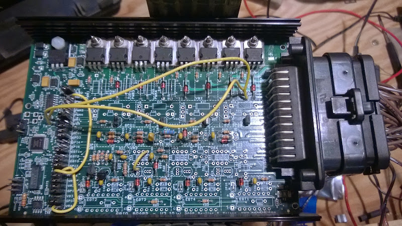
The circuit looks right to me. You might check for cold solder joints in the circuit and at the ampseal connector; and 25x2 header as well.
I would also check there there is a signal at the GPI4/AD7 jumper on the 25x2 header. Make sure you have a grounded voltage of less than 1.75 Volts, and an active signal of at least 3.25 Volts on the jumper pin on the GPI4 side.
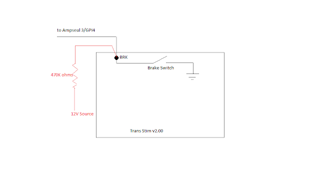
If GPI4 is a voltage divider circuit, how does it sense the brake switch being grounded?
The circuit should be attached to a switch that provides either 12V or ground (or floating). But it cannot be floating and ground, that won't work in the standard build as it has no pull-up voltage source attached. Instead the brake electrical system voltage is used as the pull-up. The circuit divides the 12V down to 5V, and this is used as 'Brake ON' for the controller, and removing the 12V allows the circuit to drop to 0V and this is recognized as Brake OFF'. (
The polarity can optionally be reversed in the user settings, of course).
If the problem with the brake indicator isn't in the soldering or voltage levels, it could be with the stim, the circuit, the code, or the INI. If you post your MSQ and a datalog I could look more closely.
Lance.
"Never wrestle with pigs. You both get dirty and the pig likes it." - George Bernard Shaw